WPWA Worm Gearbox | Horizontal Flange-Input WP Series Worm Reducer

WPWA series WP worm gearbox with horizontal IEC motor adapter. 9 ratios from i=5 to 60, output torque 19–2371 Nm, output speed 24–140 rpm, cast-iron housing, 1400 rpm input.
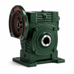
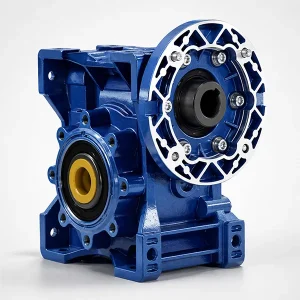
Short Description: WP series worm gearbox in the horizontal flange-input (WPWA) configuration: an IEC motor bolts directly to the gearbox face without an intermediate coupling, the most common assembly arrangement in the WP family. Output torque covers 19–2371 Nm across the WPWA50 to WPWA250 frame range, with output speeds from 24 rpm to 140 rpm at the standard 1400 rpm input. Cast-iron HT200 housing, ZQSn10-3 tin-bronze worm wheel, 20CrMnTi case-hardened worm shaft at 56–62 HRC. IEC motor flanges 56B14 through 132B5 stocked.
WPWA — The Direct-Coupled Horizontal Worm Gearbox for IEC-Motor Plants
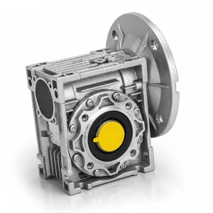
The WPWA is the horizontal flange-input variant of our WP-series cast-iron worm gear reducer family. The "A" suffix denotes the IEC motor-adapter face — an electric motor in any catalogue B5 or B14 frame size bolts directly onto the WPWA input face, with the motor shaft slipping into a coupling sleeve that drives the worm shaft inside. No external coupling, no alignment fixture, no separate motor base — the gearbox and motor become a single rigid drive package, then bolt together onto the machine frame as one assembly. This is the most common WP family configuration in Korean and Japanese industrial plants for the simple reason that 90% of motor selections come in standard IEC frame sizes already.
Mechanically the WPWA worm gear reducer covers nine ratios — i=5, 10, 15, 20, 25, 30, 40, 50, 60 — across twelve frame sizes from WPWA50 (19 Nm minimum) up to WPWA250 (2,371 Nm maximum). Output speed range is 24 rpm to 140 rpm from a 1,400 rpm 4-pole motor, the workhorse speed band for industrial conveyors, mixers, dyeing rollers, packaging-line indexers and small hoist drives. For the keyed-solid-output variant of the same internal design, see the WP series worm gearbox lineup page covering WPWDKS (vertical input) and WPWO (flange output) configurations.
Catalogue Specifications & Frame Selection Matrix
Two reference tables below cover everything needed to specify a WPWA worm gear reducer for a particular load. The property table lists materials, certifications and configuration choices common across all frame sizes. The frame matrix gives the per-frame data needed to size for actual loads — input power band, ratio range, output shaft diameter and the exact IEC motor flange the gearbox accepts. Most catalogue selections converge on three or four common frames; the unusual ones at the extremes are stocked for the heavy-duty Korean cement, glass and chemical sectors.
| Property | Specification |
|---|---|
| Gearing Arrangement | Single-stage worm — right-angle 90° axis crossing |
| Output Torque Range | 19 Nm (WPWA50, i=5) up to 2,371 Nm (WPWA250, i=60) |
| Input Speed | 1,400 rpm nominal (IEC 4-pole motor at 50 Hz) |
| Output Speed Range | 24 rpm (i=60) to 140 rpm (i=10) |
| Catalogue Ratios | i = 5, 10, 15, 20, 25, 30, 40, 50, 60 (nine standard steps) |
| Input Configuration | IEC motor flange "A" — horizontal direct-coupled. Motor shaft slip-fit into worm shaft coupling sleeve (no external coupling required) |
| Output Configuration | Keyed solid output shaft (DIN 6885 parallel key) |
| Housing | Grey cast iron HT200 — sand-cast, stress-relieved, machined to IT8 on bearing seats and IEC adapter face |
| Worm Wheel Material | ZQSn10-3 tin bronze (10% Sn, 3% Zn) per GB/T 1176 — equivalent to CuSn10Zn2 in EN 1982 |
| Worm Shaft Material | 20CrMnTi alloy steel · case-carburised 0.5–0.8 mm depth · oil-quenched · ground · 56–62 HRC |
| Output Shaft Material | C45 medium-carbon steel · induction-hardened on keyway flanks |
| IEC Motor Flanges Stocked | 56B14, 63B5, 63B14, 71B14, 80B14, 90B5, 100B5, 112B5, 132B5 |
| Lubricant | Mineral CLP 220 standard / synthetic PAG ISO VG 220 optional for sustained > 80 °C oil-bath |
| Standard Colours | RAL 3020 traffic red, RAL 5015 sky blue, RAL 7001 silver grey (custom RAL on request) |
| Industries | Manufacturing plant · construction equipment · energy & mining · ceramics · packaging · dyeing · woodworking · glass |
| Certifications | ISO 9001:2015 manufacturing certification · CE conformity declaration · material certificates per shipment |
| Warranty | 12 months from commissioning · 18 months from shipment |
Frame matrix below for the WPWA worm gear reducer: centre distance "a" (mm) is the primary capacity parameter. The "Compatible Motor Frame" column identifies the largest IEC motor that bolts directly onto each WPWA size — useful when sizing up a complete geared motor.
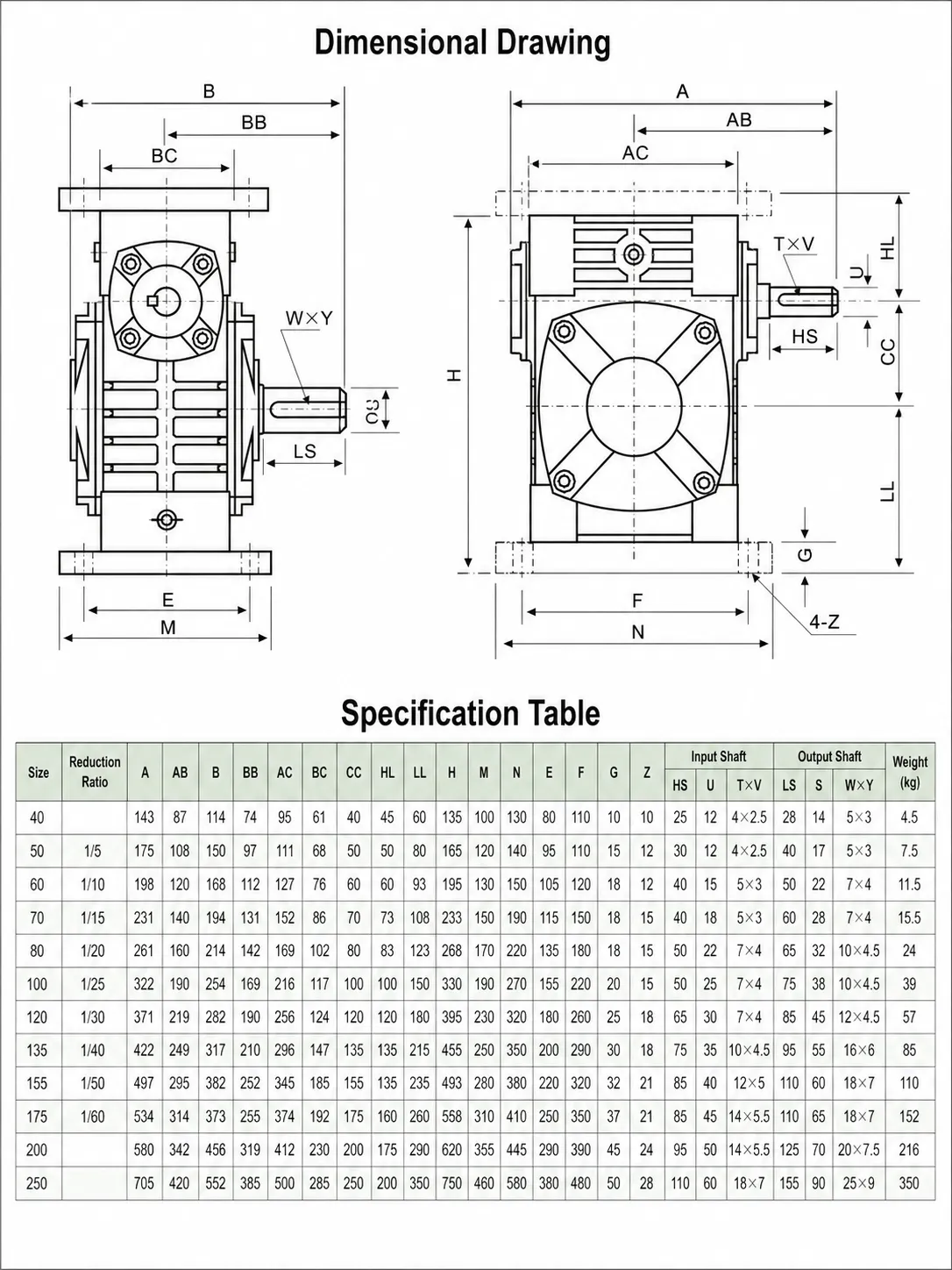
| Frame | Centre Dist. a (mm) | Input Power (kW) | Output Shaft Ø (mm) | Compatible Motor Frame | Max Output Torque (Nm) |
|---|---|---|---|---|---|
| WPWA50 | 50 | 0.12 – 0.55 | 22 | 56B14 / 63B14 | 35 |
| WPWA60 | 60 | 0.18 – 0.75 | 28 | 63B14 / 71B14 | 75 |
| WPWA70 | 70 | 0.25 – 1.5 | 32 | 71B14 / 80B14 | 140 |
| WPWA80 | 80 | 0.55 – 2.2 | 38 | 80B14 / 90B5 | 260 |
| WPWA100 | 100 | 0.75 – 4.0 | 42 | 90B5 / 100B5 | 490 |
| WPWA120 | 120 | 1.5 – 5.5 | 45 | 100B5 / 112B5 | 740 |
| WPWA135 | 135 | 2.2 – 7.5 | 50 | 112B5 / 132B5 | 1050 |
| WPWA147 | 147 | 3.0 – 11 | 55 | 132B5 | 1410 |
| WPWA155 | 155 | 4.0 – 15 | 60 | 132B5 / 160B5 | 1720 |
| WPWA175 | 175 | 5.5 – 22 | 70 | 160B5 / 180B5 | 2050 |
| WPWA200 | 200 | 7.5 – 30 | 80 | 180B5 / 200B5 | 2240 |
| WPWA250 | 250 | 11 – 30 | 100 | 200B5 / 225B5 | 2371 |
The Engineering Argument for IEC Direct-Coupled Drives
The "A" configuration is overwhelmingly the most popular WP variant in Korean and Japanese industry, and the reason is bill-of-material simplicity rather than mechanical advantage. A coupling-based worm gear reducer drive train requires four discrete items — motor, motor base, coupling, gearbox — all of which must align within tight tolerances. An IEC direct-coupled drive replaces all four with two: motor and gearbox. The motor base disappears because the motor hangs from the gearbox flange. The coupling disappears because the motor shaft slips into a precision-bored sleeve that is integral with the worm shaft.
For a Korean OEM building 200 conveyor or mixer machines per year, the WPWA worm gear reducer assembly typically saves 15–25 minutes of assembly labour per machine compared with a coupled equivalent — no laser alignment, no pillow-block bearings, no shim packs. The same simplification reduces commissioning failure modes: a misaligned coupling will sing for the lifetime of the machine and eventually destroy the gearbox bearings, whereas a slip-fit IEC adapter cannot be misaligned because the motor flange is the alignment reference.
The trade-off is that motor swap-out becomes slightly more involved. Removing a 7.5 kW IEC motor from a WPWA135 worm gear reducer means lifting roughly 60 kg of motor away from the gearbox face. For most plant maintenance teams this is a routine ten-minute job with a chain block; for installations in confined spaces or on ceiling-mounted skids, the additional clearance requirement is a planning concern at the design stage rather than a true mechanical disadvantage.

Selecting Between WPWA, WPWO and WPWDKS Variants
The three most-ordered WP-series worm gear reducer variants — WPWA, WPWO and WPWDKS — share identical worm-and-wheel internals but differ in input and output configuration. Choosing wrongly between them at the design stage causes more avoidable warranty issues than any other single decision. The selection table below summarises when each is the right specification.
| Selection Criterion | WPWA (this page) | WPWO | WPWDKS |
|---|---|---|---|
| Input configuration | Horizontal IEC flange | Horizontal IEC flange | Vertical IEC flange (motor on top) |
| Output configuration | Keyed solid shaft | Hollow bore + bolted flange | Keyed solid shaft (twin bearings) |
| Coupling required | No (motor direct-couples) | No (motor direct-couples) | No (motor direct-couples) |
| Best fit | Conveyor head pulleys, mixer paddles via separate shaft, packaging indexers | Direct mounting onto pump bodies, top-mount mixers, screw conveyor flanges | Heavy radial-load applications where output shaft needs twin bearing support |
| Floor footprint | Long horizontal envelope (motor + gearbox in line) | Compact (gearbox bolts to load) | Tall vertical envelope (motor stacked above) |
| Most common rating | 0.75–7.5 kW (the "sweet spot") | 2.2–22 kW (heavy duty) | 0.55–4 kW (medium) |
| Korean stocking depth | Highest — all 12 frames | High — frames 50–135 | Medium — frames 50–100 |
The shorthand rule we give Korean OEM specifiers: pick the WPWA worm gear reducer unless the load forces something else. The horizontal direct-coupled WPWA worm gear reducer fits the largest range of installations because most driven machines accept a coupling onto a keyed shaft. Reach for WPWO when the load offers its own input flange, and for WPWDKS when output shaft loading is so heavy that twin support bearings are warranted.
Industries & Use Cases for the WPWA Geared Motor Drive
As the most-ordered WP-series worm gear reducer variant, the WPWA worm gear reducer ships into a wider span of industries than its sibling configurations. The five sectors below cover roughly 80% of WPWA orders shipped from our Korean warehouse over the last twelve months — each with the typical motor-and-ratio combination that defines the section.
Manufacturing Plant Conveyor Drives
Belt and chain conveyors driven by a WPWA worm gear reducer carry assembled product through paint lines, automotive sub-assembly cells and electronics rework benches use the WPWA80 i=20 with a 0.55–1.1 kW motor as a near-default specification. Output speed of 70 rpm at the head pulley matches typical conveyor belt speeds of 0.25–0.4 m/s, and the cast-iron housing handles the 12–16 hour two-shift duty cycle Korean factories run.
Construction Equipment & Concrete Plant
Concrete batching plants drive their cement-feed augers with a WPWA worm gear reducer and aggregate diverter gates with WPWA135 i=40 paired with 2.2–4 kW motors. Construction-site dust ingress is the central challenge — the cast-iron housing tolerates particle abrasion that quickly destroys aluminium alternatives, and the IEC direct-couple eliminates the alignment failure mode that plagues coupled drives subjected to truck vibration.
Energy & Mining Auxiliary Drives
Coal-handling, ash-extraction and mineral-processing plants pair the WPWA175 worm gear reducer at i=50 with 5.5–7.5 kW motors on bucket elevator drives, scraper-bar conveyor heads and small slewing gears for stockpile reclaimers. The self-locking behaviour at i ≥ 30 is essential here: any reverse rotation under power loss could allow a loaded scraper to rake back toward the feed end and pile material against the head pulley.
Packaging Machinery Indexers
Form-fill-seal machines, cartoners and shrink-wrap tunnels run the WPWA60 worm gear reducer at i=15 paired with 0.37–0.75 kW motors on their main indexing axes. The worm geometry's inherent damping smooths the start-stop motion, masking encoder ripple from the closed-loop AC drives most modern packagers run. Korean food processors specify WPWA across new lines because cleanability of the painted cast-iron housing meets their internal sanitation standards.
Marine Equipment Auxiliaries
Korean shipyards specify the WPWA100 to WPWA135 worm gear reducer frames for capstan drives, winch trolleys, hatch covers and bow-thruster pitch actuators on small commercial vessels. The cast-iron housing with the polyurethane two-pack paint upgrade survives the saline atmosphere — a project lifecycle that aluminium alternatives rarely meet. We supply units with KR (Korean Register) reference documentation when buyers need it for class society approval.

Manufacturing & Assembly

Construction & Mining

Energy & Coal Handling

Marine & Shipyard
Specifying the WPWA Geared Motor Combination — Five-Step Sizing
Sizing the WPWA worm gear reducer with its motor as a complete geared-motor combination follows a five-step sequence. The procedure below catches roughly 95% of mismatch issues at quotation stage before a unit ships.
- 1
Calculate required output torque from the load. For a conveyor head pulley, T_out = F_belt × r_pulley × SF, where F_belt is belt pull at maximum loading and SF is service factor (1.0 single shift, 1.4 two-shift, 1.8 reversing). - 2
Determine target output speed. Convert the driven-machine target speed (m/s for linear loads, rpm for rotary loads) into output rpm at the WPWA shaft. For a 0.3 m/s belt over a 200 mm pulley, output speed is 28.6 rpm — pointing toward i=50 from a 1,400 rpm motor. - 3
Pick the WPWA frame from the matrix. Cross-reference the required output torque against the Max Output Torque column to find the smallest frame that handles the load. For 800 Nm continuous at SF=1.4 (1120 Nm rating needed), select WPWA135. - 4
Calculate required motor power. P_motor = (T_out × n_out) / (9550 × η × SF_motor), where η is the worm gear reducer mesh efficiency (0.70 at i=50, 0.65 at i=60) and SF_motor is 1.15 to give brief overload margin. For 800 Nm at 28 rpm, motor power is roughly 4.5 kW — round up to 5.5 kW IE3. - 5
Verify the motor flange matches the WPWA input adapter. A 5.5 kW IE3 motor sits in a 132B5 IEC flange. The WPWA135 frame supports 132B5 — confirmed match. Motor and gearbox become a single ordered package with KS-reference electrical paperwork attached.
Field Maintenance & Common Diagnostic Calls
Most WPWA worm gear reducer maintenance issues we handle through field-support fall into four recurring patterns. Each has clear early worm gear reducer warning signs and a defined fix — knowing them up front lets a plant maintenance team resolve the issue in-house rather than escalating to a supplier visit.
Symptom: housing temperature climbing above 90 °C after some weeks of duty. The most common cause is a load step-change that pushed the unit out of its thermal envelope. Reduce ambient heat input (move overhead steam pipes, add ventilation), switch from mineral CLP 220 to synthetic PAG VG 220 if not already done, or step up to the next frame size if the load is genuinely above thermal rating. Bronze wheel degradation accelerates rapidly above 95 °C oil temperature.
Symptom: oil weep at the IEC adapter face between motor and the worm gear reducer. This usually indicates a damaged or extruded O-ring at the adapter joint, often caused by over-torquing the motor mounting bolts during a previous service. Drain the oil, separate motor from gearbox, replace the O-ring with the spare from the parts kit, and re-torque to the WPWA commissioning sheet specification (not by feel).
Symptom: rising vibration over months of operation. First check is for worm gear reducer output-shaft alignment with the driven machine — most field vibration issues trace back to coupling misalignment or loosened mounting bolts on the driven side, not gearbox internals. Only after ruling those out should the worm shaft bearing pre-load be suspected; replacement of the angular-contact bearing pair is a workshop job.
Symptom: bronze powder visible at the first oil change. Light bronze coloration of the drained oil is normal during the first 100–500 hours of run-in — the worm gear reducer bronze wheel is bedding into the worm thread contact pattern. Bronze powder beyond the run-in change indicates either overload, wrong lubricant grade, or a damaged worm shaft surface. Send a 5 mL oil sample to a tribology lab for spectrographic element analysis to confirm.
Companion Components & Adjacent Reducer Families
Although the WPWA worm gear reducer integrates the motor and worm gear reducer body into one into a single direct-coupled package, the broader drive train often calls for additional components and parallel reducer families from the Korean worm gear reducer manufacturer catalogue. The four product ranges below are the most common companions or alternatives ordered alongside the WPWA — distinguishing carefully between transmission components, internal spare parts, and parallel reducer product lines.
Drive shafts (transmission companion). The WPWA worm gear reducer output shaft frequently drives its load through a coupling or short drive shaft when the gearbox cannot bolt directly to the driven machine. CV-jointed drive shafts handle small angular and parallel misalignments — useful for skid-mounted conveyor drives where the gearbox sits on the skid frame and the head pulley sits on the conveyor structure. See PTO & CV joint drive shafts for matched-length assemblies.
Worm and worm wheel pairs (internal spare parts). The bronze worm wheel and steel worm shaft inside any WPWA unit are the primary wear components. After 25,000–35,000 operating hours of duty the wheel typically reaches its wear limit while the housing and bearings remain serviceable. A re-tooth kit lets a maintenance crew restore the gearbox in place at roughly one-third the cost of a complete unit replacement. Sized for every WPWA frame at worm and worm wheel pairs.
Planetary gear reducers (sister product line). Where the application requires high mechanical efficiency (≥ 95%) or low backlash for accurate positioning — for example servo-driven indexing rotaries or precision feedscrew drives — a planetary gearbox is the appropriate alternative reducer family. Same supplier, different drive principle. See planetary gear reducers for in-line and right-angle ranges that complement the WPWA worm gear reducer where worm efficiency is insufficient.
Agricultural gearboxes (industry-specific sister line). For tractor PTO drives, irrigation pump drives, rotary tiller heads and feed-line conveyors, our agricultural gearbox catalogue applies similar bronze-wheel-and-steel-worm technology in field-rated housings with reinforced sealing for outdoor exposure. Browse agricultural gearbox replacements for sizing.

Drive Shafts (transmission companion)

Worm Gear Pairs (internal spare parts)

Planetary Gearboxes (sister product line)

Agricultural Gearboxes (sister product line)
WPWA Application & Sourcing FAQ
The questions below are the ones our applications team handles most often during quotation review for the WPWA worm gear reducer family. Each answer reflects bench-test data and field-service experience — not rewritten catalogue marketing copy.

Q: Can I bolt any IEC motor onto a WPWA gearbox, or do I have to specify the motor brand?
A: Any IEC-standard motor with the matching B5 or B14 flange code bolts onto the WPWA worm gear reducer adapter face directly — the IEC flange standard guarantees dimensional compatibility regardless of motor manufacturer. Hyosung, Higen, ABB, Siemens, Toshiba and TECO motors all fit without modification. We can supply the gearbox alone for use with customer-specified motors, or as a complete geared motor with our preferred Korean Higen or Hyosung motor brand.
Q: How does the WPWA differ from WPA, WPS, WPDA and other WP variants I see in old catalogues?
A: The "W" middle letter in WPWA designates the worm gear reducer housing variant the worm-housing variant of the WP family — the most common and widely-stocked configuration. Older WP, WPS or WPDA designations refer to legacy housing patterns from the 1970s–1990s; their dimensional standards survive but are no longer in active production. The WPWA we ship today is the modern equivalent specification. If you have an older WP unit to replace, send the original frame size and ratio and we will cross-reference to the current WPWA equivalent.
Q: What is the noise level of a typical WPWA at 1 m?
A: Bench-measured on a WPWA80 worm gear reducer at i=20 with 1.1 kW input, LpA sits at 56–60 dB. The cast-iron housing is roughly 4–6 dB quieter than the equivalent NMRV aluminium body because the graphite-flake microstructure of HT200 absorbs vibration far better than aluminium. Larger frames at lower ratios (i=10, 15) tend to run a few dB quieter still; smaller frames at i=60 are at the loud end of the band.
Q: Can I run a WPWA in reversing duty for a hoist application?
A: Yes for occasional reversal — say jam clearance — but never as the only safety device on a lifting application. Self-locking in a worm gear reducer is a friction phenomenon and is not safety-classified for lifting. Always pair the WPWA worm gear reducer with a brake motor, and add a positive roller-clutch backstop on the worm shaft input if regulatory approval requires redundancy.
Q: Can I use VFD speed control on a WPWA worm geared motor?
A: Yes — the WPWA worm gear reducer accepts VFD speed control between roughly 30% and 110% of base speed without affecting bearing life. Below 30% the splash lubrication of the worm-and-wheel mesh becomes intermittent — for sustained low-speed running below 15 Hz, switch to forced lubrication or specify a synthetic PAG fill with extended additive package. Above 110% the heat generation rises non-linearly and the thermal margin shrinks rapidly.
Q: What is the typical service life on a 16-hour two-shift duty?
A: A correctly sized WPWA worm gear reducer running at SF=1.4 at i ≤ 50 with synthetic PAG and 4,000-hour oil intervals delivers 30,000–45,000 operating hours before bronze wheel wear-limit replacement. That is roughly 7–11 years of two-shift duty. Worm shaft and tapered roller bearings last roughly twice as long; cast-iron housing service life is effectively the life of the plant.
Q: What documentation ships with each WPWA unit?
A: Every WPWA worm gear reducer ships with the factory test record (signed by the QC inspector and traceable to the worm shaft heat-treatment and bronze wheel casting batches), an installation and commissioning sheet specifying torque values, the lubricant SDS, the ISO 9001 manufacturing certificate and the CE conformity declaration. Material certificates for the bronze wheel and worm shaft are issued on request at no extra charge.
Q: How fast can WPWA frames be delivered into Korea?
A: WPWA worm gear reducer frames 50 through 135 — by far the most common selections — are typically ex-stock at our Korean warehouse with 2–5 working day delivery to most industrial cities. Frames WPWA147 to WPWA250 ship on 3–4 week lead time from the Hangzhou production line. Custom paint, output shaft modifications or backstop fitments add roughly 2 weeks.
Operator & Engineer Reports from Asian Plants
Feedback below is collated from process engineers, plant maintenance leads and OEM designers who have specified WPWA units across Korea, Japan, Vietnam and Thailand over the past 12–18 months from WPWA worm gear reducer installations. Where customers gave written permission, technical detail and frame size are preserved verbatim alongside the worm gear reducer model code and operating context.
Park Min-jun, Mechanical Engineering Lead, Ulsan automotive sub-assembly plant (Q1 2026)
"Standardised on WPWA80 i=20 with 1.1 kW Higen motors across our paint-line conveyor fleet — eight units installed last spring. Direct-couple eliminated the laser alignment step that the previous coupled drives required. Cut commissioning labour by about 18 minutes per machine, which adds up across a 40-conveyor refit."
Han Do-yoon, Plant Maintenance Engineer, Cheongju cement batch plant (Q4 2025)
"Replaced four old coupled WP-style drives on our cement-feed augers with WPWA135 i=40 plus 4.0 kW IE3 motors. The dust-sealing on the IEC adapter face has been better than the old shaft-and-coupling drives — five months in, no fines getting into the worm bearing. Maintenance budget is dropping accordingly."
Sato Aiko, Process Engineer, Hiroshima coal-handling plant (Q3 2025)
"Six WPWA175 i=50 units on stockpile reclaimer scraper drives. The self-locking ratio at i=50 is the feature that mattered most — power dips at our site are common and we cannot risk a 6-tonne scraper raking back into the feed end. Three months in, no reverse-rotation incidents and oil temperature stable at 72 °C."
Lee Ji-woo, OEM Equipment Designer, Seoul packaging machine builder (Q4 2025)
"Specified WPWA60 i=15 with 0.55 kW VFD-controlled motors across our new flow-wrap product line. The closed-loop speed control plus worm damping gives us ±0.2% film registration on the encoder — better than we expected. Delivery from Korean stock was three working days."
Kim Seo-yun, Procurement Engineer, Busan shipyard (Q2 2025)
"Twelve WPWA100 i=30 with polyurethane two-pack paint upgrade for a coastal patrol vessel hatch-cover drive contract. KR (Korean Register) reference documentation arrived inside three days from quotation acceptance — that was the differentiator over our previous European supplier."
Tran Thi Mai, Plant Engineer, Haiphong steel mill (Q3 2025)
"Three WPWA200 i=40 with 22 kW IE3 motors drive scrap-handling magnet positioning on our melt shop. Heavy reversing duty so we accepted SF=1.8 and stepped up one frame from the calculated minimum. Eight months in, no thermal flags and the cast-iron housing has shrugged off the dust environment that destroyed our previous European-brand units inside two years."
Naree Wattana, Maintenance Lead, Map Ta Phut petrochemical complex (Q3 2025)
"Standardised on WPWA120 i=30 across our utility-conveyor fleet. The IEC direct-couple means motor swap-outs during scheduled maintenance take ten minutes rather than the hour-plus a coupled drive required for re-alignment. Four units running 18 months continuous, no oil weep, no temperature alarms."
Additional information
| Editor | Cxm |
|---|
Related products
-
EP-NMRV Aluminum Worm Gearbox with Output Flange | RV-Series Worm Gear Reducer
-
FU1000 Worm Gearbox Replacement | Fenner FU-Type Horizontal Foot-Mount Equivalent
-
WPWO Worm Gearbox | Output-Flange WP Series Worm Reducer
-
WPWDKS Worm Gearbox | Vertical-Input WP Series Worm Reducer
-
MRV050 Worm Gear Reducer | Worm Gearbox


