WPWO Worm Gearbox | Output-Flange WP Series Worm Reducer

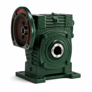
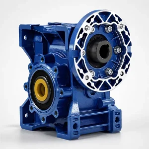
WP series worm gearbox in the output-flange (WPWO) configuration: cast-iron housing, hollow output bore with bolted PCD flange face, suitable for direct mounting onto pump bodies, mixer assemblies and screw-conveyor drive ends. Nine catalogue ratios from i=5 to i=60, output torque 19–2745 Nm across the full frame range, rated power 0.12 kW up to 33.2 kW. Worm wheel in ZQSn10-3 tin bronze; 20CrMnTi case-hardened worm shaft at 56–62 HRC. IEC motor flanges from 56B14 through 132B5 in stock.
WPWO — The Flange-Mount Variant of the WP Worm Gearbox Family
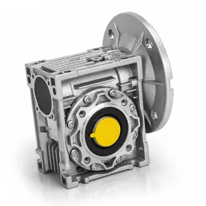
The WPWO is the output-flange variant of our WP-series cast-iron worm gear reducer. Where the WPWDKS configuration drives a load through a keyed solid output shaft, the WPWO presents a hollow output bore with a bolted PCD flange face — the gearbox bolts directly onto the load housing rather than connecting through a coupling. Common targets include vertical pump bodies, mixer assemblies, screw-conveyor drive ends, slewing-ring drives on small cranes, and any application where the driven machine carries its own input shaft and the gearbox is designed to mate flush with it.
The WPWO worm gear reducer covers a wider torque envelope than any other WP variant in our catalogue: 19 Nm at the smallest WPWO50 frame at i=5, scaling all the way to 2,745 Nm at the WPWO250 frame at i=60. Rated input power runs from 0.12 kW (a small mixer auxiliary) up to 33.2 kW (a heavy bag-house screw conveyor). Output speeds span 19 rpm to 186.7 rpm from a 1,400 rpm input — the natural range for slow-speed industrial machinery. For other variants in the WP family, see our broader WP series worm gearbox lineup including WPWA (horizontal flange input) and WPWDV (vertical-output) configurations.
Catalogue Specifications & Frame Capacity
The first table below lists the catalogue specification of the WPWO worm gear reducer family — gearing arrangement, torque and power range, materials of the principal wear components, and motor-flange options. The second table is the frame-by-frame capacity matrix: pick a frame, read the input power band the housing supports, and cross-reference the output-flange PCD that mates with your driven machine. PCD (pitch circle diameter) is the dimension to specify when ordering — the bolt pattern is what determines whether the gearbox bolts cleanly onto the existing flange, so it is worth measuring carefully before quotation.
| Property | Specification |
|---|---|
| Gearing Arrangement | Single-stage worm — right-angle 90° axis crossing |
| Output Torque | 19 Nm (WPWO50, i=5) up to 2,745 Nm (WPWO250, i=60) |
| Rated Input Power | 0.12 kW – 33.2 kW (frame-size dependent) |
| Input Speed | 1,400 rpm nominal (4-pole IEC motor) |
| Output Speed Range | 19 rpm (i=60) up to 186.7 rpm (i=7.5) |
| Catalogue Ratios | i = 5, 10, 15, 20, 25, 30, 40, 50, 60 (nine standard steps) |
| Output Configuration | Hollow bore with bolted output flange (the "O" in WPWO denotes Output-flange) |
| Housing | Grey cast iron HT200 — sand-cast, stress-relieved, machined to IT8 on bearing seats and flange face |
| Worm Wheel | ZQSn10-3 tin bronze (10% Sn, 3% Zn) per GB/T 1176, equivalent to CuSn10Zn2 in EN 1982 |
| Worm Shaft | 20CrMnTi alloy steel · case-carburised 0.5–0.8 mm · oil-quenched · ground · 56–62 HRC |
| Output-Flange Material | C45 medium-carbon steel · induction-hardened on bolt-hole margins |
| Bearings | Worm: angular-contact paired set absorbing axial thrust. Output: tapered roller bearings sized for the radial moment of an overhanging flange-mounted load |
| IEC Motor Flanges | 56B14, 63B5, 63B14, 71B14, 80B14, 90B5, 100B5, 112B5, 132B5 |
| Lubricant | Mineral CLP 220 standard fill / synthetic PAG ISO VG 220 optional for sustained > 80 °C oil-bath |
| Standard Colours | RAL 6005 moss green, RAL 5015 sky blue, RAL 7001 silver grey (custom RAL on request) |
| Warranty | 12 months from commissioning · 18 months from shipment |
Frame-size matrix below for the WPWO worm gear reducer: centre distance "a" (mm) defines mechanical capacity. Output-flange PCD is the dimension to verify against the driven machine before placing an order.
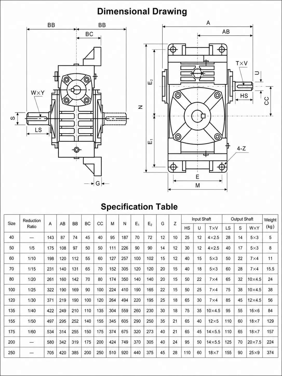
| Frame | Centre Dist. a (mm) | Input Power (kW) | Output Bore Ø (mm) | Output Flange PCD (mm) | Max Output Torque (Nm) |
|---|---|---|---|---|---|
| WPWO50 | 50 | 0.12 – 0.55 | 22 | 100 / 4-M6 | 35 |
| WPWO60 | 60 | 0.18 – 0.75 | 28 | 120 / 4-M8 | 82 |
| WPWO70 | 70 | 0.25 – 1.5 | 32 | 140 / 4-M8 | 155 |
| WPWO80 | 80 | 0.55 – 2.2 | 38 | 160 / 4-M10 | 285 |
| WPWO100 | 100 | 0.75 – 4.0 | 42 | 200 / 4-M12 | 540 |
| WPWO120 | 120 | 1.5 – 5.5 | 45 | 220 / 4-M12 | 820 |
| WPWO135 | 135 | 2.2 – 7.5 | 50 | 240 / 4-M14 | 1180 |
| WPWO147 | 147 | 3.0 – 11 | 55 | 260 / 4-M14 | 1620 |
| WPWO155 | 155 | 4.0 – 15 | 60 | 280 / 4-M16 | 1980 |
| WPWO175 | 175 | 5.5 – 22 | 70 | 300 / 6-M16 | 2380 |
| WPWO200 | 200 | 7.5 – 30 | 80 | 340 / 6-M18 | 2580 |
| WPWO250 | 250 | 11 – 33.2 | 100 | 380 / 6-M20 | 2745 |
Why a Flange Output Matters — Mechanical Logic of the WPWO
A flange-output worm gear reducer eliminates one of the most failure-prone elements of a typical drive train: the coupling between gearbox output shaft and driven machine input shaft. Couplings — even good elastomeric ones — introduce backlash, demand careful angular and parallel alignment during commissioning, and are the first thing to fail under shock-load conditions. The WPWO sidesteps the issue by clamping its output flange directly to the driven machine. The result is shorter installed length, fewer alignment steps at commissioning, and a cleaner moment-load path through the driven machine's own bearings.
There is a structural cost to this elegance. Because the output bore now carries the radial moment of the driven machine — the load no longer sits on a separate bearing — the WPWO worm gear reducer output bearings must be sized larger than equivalent solid-shaft units. We use tapered roller bearings rather than deep-groove ball bearings on the output side for exactly this reason; the tapered roller pair handles both axial and radial moment loading without complaint. For a vertical mixer drive, this is critical: the mixer impeller weight, the radial fluid drag, and the axial down-thrust all enter the gearbox at the same flange face.
A common mistake new worm gear reducer specifiers make is treating WPWO and WPWDKS as interchangeable on the basis of frame size and ratio alone. They are not. The WPWO output flange is a structural member, not a connection convenience. Specify WPWO when the driven machine has its own bearings and you want the gearbox to bolt onto an existing flange face. Specify WPWDKS when you need a free-standing solid output shaft that drives through a coupling to a bearing-mounted load.

Heat Generation, Thermal Power & Sizing for Continuous Duty
Sizing a WPWO worm gear reducer for a continuous-duty mixer or pump drive requires considering thermal capacity alongside torque capacity. A WP-style worm gear reducer has two distinct power ratings the catalogue does not always emphasise. The first is mechanical rated power — the load the gear teeth, bearings and shafts can carry without breaking under SF=1.0 loading. The second is thermal rated power — the heat the housing can dissipate to ambient air without the oil bath exceeding its degradation temperature.
For a single-stage WPWO worm gear reducer at i=40, mesh efficiency sits around 70%. A 5.5 kW input therefore generates 5.5 × 0.30 = 1.65 kW of waste heat, all of which has to leave the housing through convection and radiation. At 25 °C ambient with a still-air installation, a WPWO135 cast-iron housing dissipates roughly 1.4 kW thermally. For the worm gear reducer that is below the 1.65 kW heat generation — meaning the unit cannot run continuously at its mechanical rating without auxiliary cooling. Either step up to WPWO147 (next frame, more housing surface), add forced-air ventilation, or accept that the unit can only run intermittently at 5.5 kW input.
This is the trap that catches first-time WP-series worm gear reducer specifiers and is why our application form asks for ambient temperature, duty cycle and hours-per-day before quoting. The mechanical rating column in the frame-size table assumes intermittent operation; for continuous duty above 12 hours per day, derate by a factor between 0.7 (45 °C ambient, sealed enclosure) and 0.9 (25 °C ambient, open ventilation). Specify the actual operating environment and we will return a thermally validated frame size, not just a mechanically-sufficient one.
Where the Flange-Output Geometry Earns Its Premium
The WPWO worm gear reducer is selected for applications where the load offers its own input flange and a coupling-free drive train is preferable. The five sectors below cover roughly 85% of WPWO orders shipped to Korean and regional industrial customers over the last twelve months.
Vertical Mixer & Agitator Drives
Top-mounted mixer drives in chemical, paint and food-processing tanks bolt directly to the WPWO output flange. The mixer column hangs from the flange via a stub shaft, and the bronze wheel inside the WPWO worm gear reducer absorbs the down-thrust from the impeller. The WPWO100 worm gear reducer at i=30 with a 1.5 kW motor is the workhorse for 200–400 L tank mixers; WPWO155 i=20 with 5.5 kW handles 1,000–2,000 L industrial agitators.
Vertical Pump Body Drives
Vertical-shaft sewage pumps, slurry pumps and viscous-fluid lobe pumps mount the WPWO directly onto the pump head. A WPWO80 or WPWO100 worm gear reducer at i=10 paired with a 0.75–2.2 kW motor delivers the 140–187 rpm range that most positive-displacement pumps need. The flange mount eliminates the stuffing-box realignment ritual that plagues coupled pump drives.
Screw Conveyor Drive Ends
Bag-house dust handling, cement clinker conveyance and sludge-removal screws all feed into a flange-mounted worm gear reducer end with a flanged drive boss that mates to the WPWO. WPWO135 to WPWO250 frames cover screw conveyors from 250 mm to 600 mm trough width. The self-locking i ≥ 30 ratios prevent reverse-drive of the screw column under power loss — important when the conveyor is full and a backflow could overload the discharge end.
Slewing Drives on Small Cranes & Manlifts
A WPWO worm gear reducer driving a slewing-ring pinion provides positive holding torque provides positive holding torque without an external brake on small jib cranes, telescopic manlifts and warehouse stacker cranes. The flange output drives a pinion shaft that engages the slewing-ring gear teeth directly — typical configuration is WPWO120 i=50 with a 1.5 kW brake motor.
Cooling Tower Fan & Damper Drives
For industrial cooling-tower variable-pitch damper actuators a worm gear reducer in WPWO80 or WPWO100 frame size and small cell-fan slow-speed drives use the WPWO80 or WPWO100 flange-mounted to the damper hub. Outdoor weatherproofing and the corrosion-resistant cast-iron housing handle the wet ambient that destroys aluminium-bodied alternatives within a year or two.


WPWO Flange-Mount Installation Best Practices
Installing a flange-output worm gear reducer differs from a coupled drive in a few small but critical ways. Following the four-step procedure below at commissioning prevents the most common warranty issues we see on returned units.
- 1
Verify flange face perpendicularity. Measure the perpendicularity of the driven machine's mating flange to the input shaft axis. Acceptable tolerance is 0.05 mm per 100 mm of PCD. If it exceeds that, the WPWO output bearing will see edge-loading from day one and bearing life will fall by 60–80%. - 2
Tighten flange bolts in cross-pattern sequence. Use a torque wrench, two passes — first pass at 50% of final torque, second pass to full torque. The cross-pattern sequence avoids cocking the flange face. Final torque values are listed on the WPWO commissioning sheet shipped with each unit. - 3
Confirm input-shaft fit before driving the bolt train home. If the driven machine's input shaft does not slide into the WPWO output bore with light thumb pressure, do not force it. Forcing causes the worm wheel to side-load the worm shaft on day one. Re-machine the input shaft slightly undersized rather than risk premature wheel wear. - 4
Run the worm gear reducer unloaded for one hour, then check oil level. Run the WPWO worm gear reducer at no-load for 60 minutes after commissioning. Stop, wait 30 minutes for air to settle out of the bath, and verify oil level on the sight glass. Top up if necessary — first running often shows the oil level dropping by 3–5 mm as air pockets clear.
Quality Certification & Acceptance Testing
Every WPWO worm gear reducer leaving the worm gear reducer production line passes a four-stage acceptance test. The first is dimensional inspection — bearing seats, output flange runout, motor flange bolt pattern, all measured against ISO 9001-controlled drawings. The second is no-load run-in: 30 minutes at rated input speed in both rotational directions, monitoring temperature rise and listening for bearing noise. The third worm gear reducer test is the loaded test: 60 minutes at 75% of rated input power, monitoring oil temperature stabilisation. The fourth is a final visual and seal-leak check after 24 hours of cool-down.
The factory test record ships with every WPWO worm gear reducer unit, signed by the QC inspector and traceable to the worm shaft heat-treatment batch and bronze wheel casting heat. Korean customers requiring third-party witness inspection on critical orders — typically WPWO175 frames upwards used in chemical mixer drives — can specify a Bureau Veritas, SGS or TÜV witness at quotation stage; the cost is added per-unit and arranged through their Korean offices to keep audit logistics simple.
Standard certifications shipping with every unit include the ISO 9001:2015 manufacturing certificate, the CE conformity declaration for sale into the European Economic Area, and material certificates for the worm shaft (20CrMnTi heat-treatment batch) and bronze wheel (ZQSn10-3 casting heat). Korean Industrial Standard (KS) reference documentation is available on request for buyers needing it for KS-marked end-machine assembly.
Drive-Train Complements & Sister Reducer Lines
Drive trains around a WPWO worm gear reducer typically combine a worm gear reducer with three categories of supplementary product with three categories of supplementary product, plus one parallel reducer line from our Korean worm gear reducer manufacturer catalogue. The four below are listed in order of how often they appear together with WPWO units on the same purchase order.
Drive shafts (transmission companion). Although the WPWO output mounts directly to the driven machine, the input side often connects to its motor via a drive shaft when the motor is remote — typical of installations where the motor sits at floor level and the gearbox is high above on a mixer or pump skid. Telescopic and CV-jointed drive shafts handle the small angular and axial misalignments inevitable on welded skid frames. See PTO & CV joint drive shafts for matched-length assemblies.
Worm and worm wheel pairs (internal spare parts). The bronze worm wheel and steel worm shaft are the principal wear components inside any WPWO unit. After 25,000–35,000 hours of duty, the wheel typically reaches its wear limit while the cast-iron housing and tapered roller bearings remain serviceable. A worm-and-wheel rebuild kit lets a maintenance team restore the gearbox in place at roughly one-third the cost of a complete unit replacement. Sized for every WPWO frame at worm and worm wheel pairs.
Planetary gear reducers (sister product line). Where the application requires high mechanical efficiency (≥ 95%) or very low backlash for accurate positioning — for example servo-driven indexing rotaries or precision agitator-shaft positioning — a planetary reducer is the right alternative family. Same supplier, different drive principle. See planetary gear reducers for in-line and right-angle ranges that complement the WPWO worm gear reducer where worm efficiency is insufficient.
Agricultural gearboxes (industry-specific sister line). For tractor PTO drives, irrigation pump drives, feed-line conveyors and rotary tiller heads, our agricultural gearbox catalogue applies similar bronze-wheel-and-steel-worm technology in field-rated housings with reinforced sealing for outdoor exposure. Browse agricultural gearbox replacements for sizing.

Drive Shafts (transmission companion)

Worm Gear Pairs (internal spare parts)

Planetary Gearboxes (sister product line)

Agricultural Gearboxes (sister product line)
WPWO Specification & Sizing FAQ
The questions below are the ones our applications team handles most often during quotation review and post-installation support for the WPWO worm gear reducer family. Answers reflect bench-test data and field experience rather than catalogue marketing language.

Q: What does the "O" in WPWO stand for, and how is it different from WPWDKS or WPWDA?
A: The "O" denotes Output-flange — the gearbox terminates in a hollow bore plus bolted flange face rather than a solid keyed shaft. WPWDKS is keyed-solid output with vertical motor input; WPWDA is keyed-solid output with horizontal flanged motor input. WPWO has flange output that bolts directly onto the driven machine. All three share identical worm-and-wheel internals — the housing casting and output side differ.
Q: How do I confirm the WPWO output flange will bolt onto my existing pump or mixer body?
A: Specify the PCD (pitch circle diameter), bolt count and bolt thread of the existing flange face on your pump or mixer body. Cross-reference to the WPWO frame-size table — the catalogue values are listed alongside each frame. If your existing flange does not match a catalogue PCD, we can supply a custom-machined adapter plate or bore the WPWO output flange to a non-standard PCD on orders of 5 units or more.
Q: What is the maximum continuous output torque the WPWO worm gear reducer can handle?
A: For the largest WPWO250 worm gear reducer at i=60 with synthetic PAG lubrication and SF=1.0, the catalogue value is 2,745 Nm. For continuous duty (16+ h/day), apply the thermal derating factor we describe in the sizing module — practical continuous output is 70–90% of catalogue depending on ambient temperature and ventilation.
Q: Can the WPWO be supplied with a backstop for inclined screw conveyors?
A: Yes. A roller-clutch backstop on the worm gear reducer worm shaft input is offered as a factory-fit option on all WPWO frames from 80 upwards. The backstop is rated for the rated torque of the gearbox and provides positive anti-reverse holding under power loss. Specify at order stage; field retrofitting is possible but requires gearbox disassembly.
Q: How does the WPWO axial thrust capacity compare to the radial?
A: The tapered roller bearings on the worm gear reducer output side carry both. Axial thrust capacity is roughly 0.8 times the radial capacity at the WPWO80 frame, scaling proportionally with frame size. For mixer applications with significant axial down-thrust (impeller drag plus column weight), specify the axial thrust at quotation; some applications benefit from an output flange variant with separately specified thrust bearings.
Q: Is the WPWO suitable for outdoor cooling-tower duty?
A: Yes, with the standard epoxy paint finish and sealed Viton lip seals. For coastal saline environments or sustained chlorine vapour exposure, specify the two-pack polyurethane coating option and stainless-steel external fasteners. We have WPWO100 and WPWO135 units running on cooling-tower damper drives at Korean petrochemical sites without paint failure after 4+ years.
Q: What replacement parts wear out first, and how long do they last?
A: The bronze worm wheel inside a WPWO worm gear reducer is the first to reach its wear limit, typically at 25,000–35,000 operating hours under SF=1.0 duty. Worm shaft and tapered roller bearings last roughly twice as long. Output-flange seal lip wear shows up as oil weep around the flange face — replacement is a 30-minute job in place. Housing service life is effectively the life of the plant.
Q: Lead time and stocking position for WPWO frames into Korea?
A: WPWO worm gear reducer frames 50 through 135 are typically ex-stock at our Korean warehouse with 2–5 working day delivery to most industrial cities. WPWO147 through WPWO250 ship on 3–4 week lead time from the Hangzhou production line. Custom outputs, paints or backstops add roughly 2 weeks to either case.
Field Reports from Industrial Plants
Feedback below is from process engineers, plant maintenance leads and OEM designers across Korea, Japan, Vietnam and Thailand who specified or serviced WPWO units over the past 12–18 months. Where customers have given written permission, technical detail and frame size are preserved verbatim alongside the worm gear reducer frame size.
Lee Ji-woo, Process Engineer, Yeosu petrochemical plant (Q1 2026)
"Twelve WPWO135 i=30 units installed on chemical reactor agitators last summer. Eight months of three-shift duty later, the worm gear reducer oil temperature is averaging 71 °C with the 4.0 kW IE3 motors — well within limit. Flange-mounted means no coupling realignment after thermal cycling, which used to cost us a maintenance hour per unit per quarter."
Tanaka Hiroshi, Equipment Designer, Osaka mixer OEM (Q4 2025)
"Standardised the WPWO80 worm gear reducer at i=20 across our 200 L laboratory mixer product line. Output flange PCD 160 with 4-M10 matched our existing housing casting exactly — no machined adapter needed. Documentation pack including the test record arrived with each shipment, which simplified our final assembly QC."
Han Do-yoon, Maintenance Lead, Pohang cement plant (Q3 2025)
"Six WPWO175 worm gear reducer units at i=50 with backstops drive the cement clinker screw conveyors at our raw-mill outfeed. Fourteen months on three-shift duty in dust-laden air — still inside the 1,800-hour oil interval and no seal weep. Specified the polyurethane two-pack paint upgrade and that has held up against the alkaline cement dust."
Nguyen Thi Lan, Plant Engineer, Haiphong fertiliser plant (Q3 2025)
"Two WPWO250 units replaced a Korean-brand drive that failed at 8 years on a 600 mm urea screw conveyor. The PCD on the new flange matched the existing casting within tolerance, no adapter plate. The backstop spec is the feature that justified the higher price — power loss in this plant is frequent and the chip column drops hard without it."
Choi Hyun-woo, OEM Designer, Daegu pump plant (Q4 2025)
"Designed a new vertical sewage pump range around the WPWO100. The output bore tolerance was tight enough to slip-fit the pump shaft without adapter sleeve — that simplification cut 12 minutes of assembly time per unit. Catalogue test data matched our bench measurements within 4% on torque output."
Naree Wattana, Plant Engineer, Map Ta Phut chemical complex (Q3 2025)
"Four WPWO155 i=40 units on cooling tower damper actuators, replacing failed European-brand units. Fifteen months in coastal saline air, and the polyurethane coating has held up. Self-locking holds the dampers steady against wind load without needing a separate brake — that simplified our control wiring."
Kim Seo-yun, Procurement Engineer, Incheon chemicals (Q1 2026)
"Quotation for WPWO120 came back inside 24 hours with the 3D STEP file attached. Material certificates for the bronze wheel and worm shaft arrived with the shipment, which our QA team needs for our ISO audit pack. Two units on a slurry pump drive, six months in, no complaints."
Additional information
| Editor | Cxm |
|---|
Related products
-
EP-NMRV Aluminum Worm Gearbox with Output Flange | RV-Series Worm Gear Reducer
-
FU1000 Worm Gearbox Replacement | Fenner FU-Type Horizontal Foot-Mount Equivalent
-
WPWA Worm Gearbox | Horizontal Flange-Input WP Series Worm Reducer
-
WPWDKS Worm Gearbox | Vertical-Input WP Series Worm Reducer
-
MRV050 Worm Gear Reducer | Worm Gearbox


