WPWDKS Worm Gearbox | Vertical-Input WP Series Worm Reducer

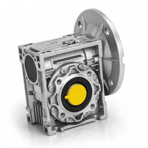
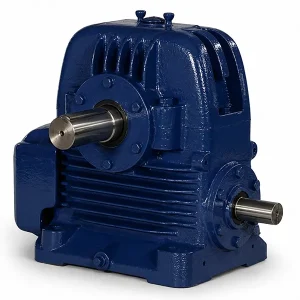
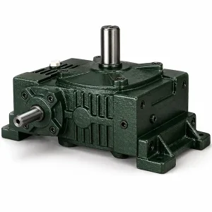
WP series worm gearbox in the WDKS configuration: vertical motor input shaft, double-bearing-supported output, keyed solid output shaft. The cast-iron housing dissipates heat far better than aluminium, which suits sustained 8–24 h/day duty in dyeing, woodworking and ceramics plants. Eight catalogue ratios (i=10, 15, 20, 25, 30, 40, 50, 60), ZQSn10-3 tin-bronze worm wheel, case-hardened 20CrMnTi worm shaft at 56–62 HRC, and IEC motor flanges from 56B14 through 80B14 in stock.
WPWDKS — Vertical-Input Cast-Iron Worm Gearbox for Heavy Industrial Duty
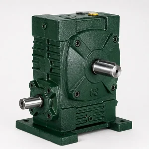
The WPWDKS is a member of the WP family of right-angle worm reducers, distinguished by its vertical motor input shaft (the "S" in the model code) and double-bearing-supported solid output shaft (the "DK" prefix). Where the lighter aluminium NMRV / RV ranges suit packaging and door-actuator duty, the WPWDKS worm gear reducer is built for plants that run their drives 16 to 24 hours a day — dyeing lines, woodworking jointers, ceramic kiln roller drives, plastic extruder feed augers, and the long horizontal indexing axes on glass float lines. The cast-iron housing is the headline difference: roughly three times the thermal mass of an aluminium body of equal frame size, which keeps oil-bath temperatures below 80 °C even on continuous-duty mineral-oil installations.
Eight catalogue ratios — i=10, 15, 20, 25, 30, 40, 50, 60 — cover input speeds from a 4-pole motor (1450 rpm) down to output speeds between 24 rpm and 145 rpm. Input power matches IEC frames from 56B14 (0.12 kW) up to 80B14 and beyond (15 kW on the larger frame sizes). Korean industrial buyers most often source the WPWDKS as a direct fit-and-function replacement for legacy WP-series worm reducers from regional brands; the IEC flange standard means a swap usually requires no machined adapter plate. See the rest of the WP series worm gear box lineup for matching WPWDA (horizontal input) and WPWDV (vertical output) variants.
Technical Specifications & Material Data
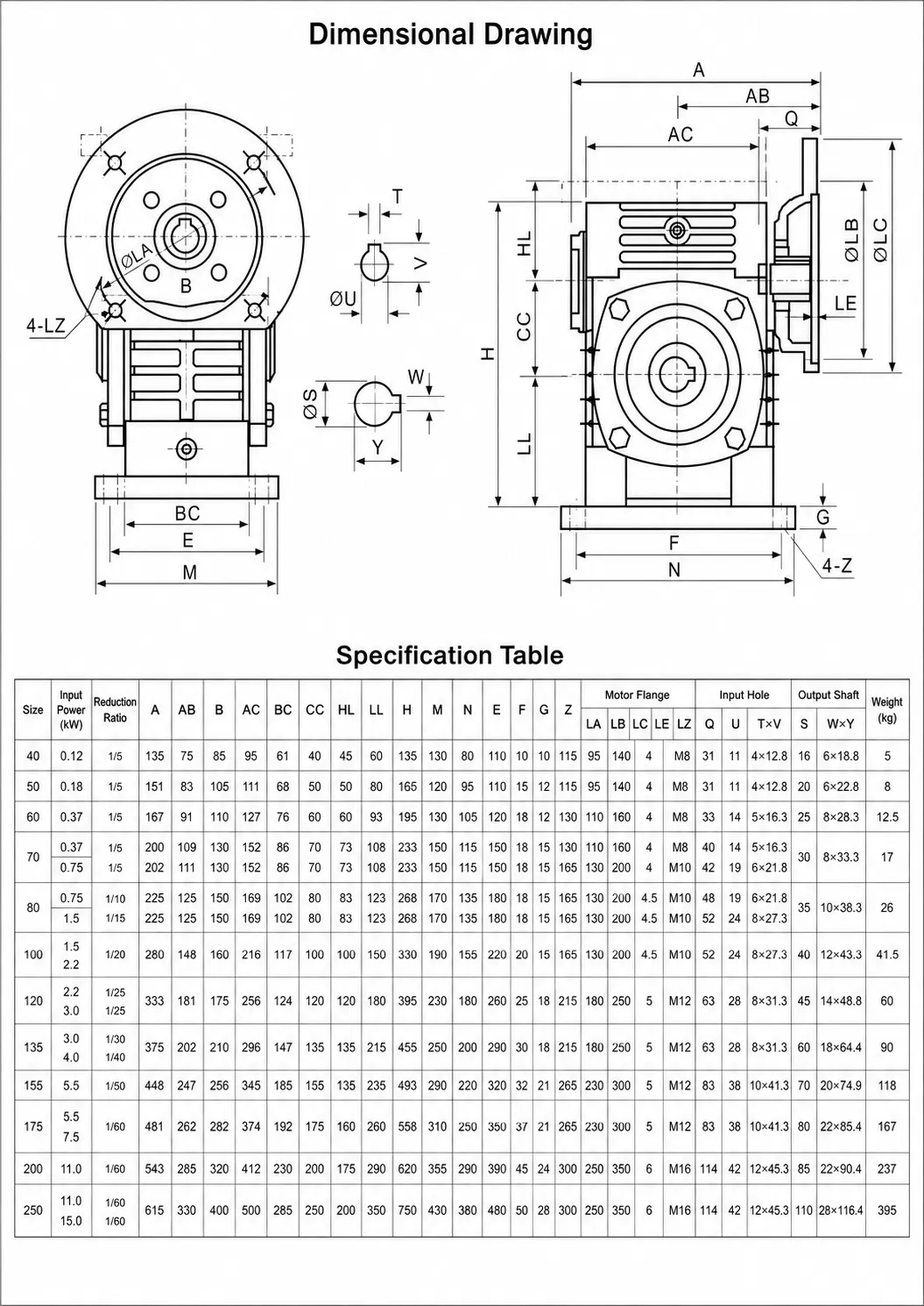
The first table below lists the catalogue specification — model identifiers, ratio range, materials of the principal wear components, lubricant, packaging and motor-flange options. The second table is the frame-size matrix: pick a centre-distance, read the input power band the housing supports, and cross-reference the catalogue ratios. Centre distance is the dimension that determines mechanical capacity on every WP-style worm gearbox.
| Property | Specification |
|---|---|
| Type | Right-angle worm gearbox / worm gear reducer |
| Model series | WPWDKS — vertical motor input, double-bearing-supported keyed solid output |
| Catalogue ratios | i = 10, 15, 20, 25, 30, 40, 50, 60 |
| Input power range | 0.12 kW – 15 kW (frame-size dependent) |
| IEC motor flanges | 56B14, 63B5, 63B14, 71B14, 80B14, 90B5, 100B5, 112B5 |
| Housing material | Grey cast iron HT200 — sand-cast, stress-relieved, machined to IT8 tolerance on all bearing seats |
| Worm wheel material | ZQSn10-3 tin bronze (10% Sn, 3% Zn) — equivalent to CuSn10Zn2 in EN 1982. Centrifugally cast for dense, defect-free working diameter. |
| Worm shaft material | 20CrMnTi alloy steel · case-carburised 0.5–0.8 mm depth · oil-quenched · ground · 56–62 HRC at the contact face |
| Output shaft material | Tempered medium-carbon steel C45 (45#) · induction-hardened on the keyway flanks |
| Bearings | Worm shaft: angular-contact paired set absorbing axial thrust. Output shaft: tapered roller bearings supporting both ends (hence "DK" — double-bearing keyed). |
| Lubricant | Mineral CLP 220 (factory standard) or synthetic PAG ISO VG 220 (option for > 80 °C ambient) |
| Standard colour | RAL 5015 sky blue or RAL 7001 silver grey (custom colours quoted on request) |
| Industrial usage | Dyeing & finishing · ceramics · plastic extrusion · woodworking · glass float lines · packaging · chemicals |
| Standard warranty | 12 months from commissioning · 18 months from shipment |
Frame-size matrix below for the WPWDKS worm gear reducer: centre distance "a" (mm) defines mechanical capacity. The input power band assumes 4-pole motor at 1450 rpm and SF=1.0 uniform load — apply derating factors below for non-standard duty.
| Frame | Centre Dist. a (mm) | Input Power (kW) | Ratio Range | Output Shaft Ø (mm) | IEC Flange |
|---|---|---|---|---|---|
| WPWDKS50 | 50 | 0.12 – 0.55 | 10 – 60 | 22 | 56B14 / 63B14 |
| WPWDKS60 | 60 | 0.18 – 0.75 | 10 – 60 | 28 | 63B14 / 71B14 |
| WPWDKS70 | 70 | 0.25 – 1.5 | 10 – 60 | 32 | 71B14 / 80B14 |
| WPWDKS80 | 80 | 0.55 – 2.2 | 10 – 60 | 38 | 80B14 / 90B5 |
| WPWDKS100 | 100 | 0.75 – 4.0 | 10 – 60 | 42 | 90B5 / 100B5 |
| WPWDKS120 | 120 | 1.5 – 5.5 | 10 – 60 | 45 | 100B5 / 112B5 |
| WPWDKS135 | 135 | 2.2 – 7.5 | 10 – 60 | 50 | 112B5 / 132B5 |
| WPWDKS147 | 147 | 3.0 – 11 | 10 – 60 | 55 | 132B5 |
| WPWDKS155 | 155 | 4.0 – 15 | 10 – 60 | 60 | 132B5 / 160B5 |
What the Letter Suffix Tells You — Reading the WP Model Code
WPWDKS worm gear reducer model codes are not arbitrary — every letter signals a specific configuration choice. Misreading the code is one of the most common reasons a wrong unit ships against an OEM order. The WPWDKS worm gear reducer suffix decomposes as follows: WP = the broad worm-reducer family; W = the worm housing variant; D = double-bearing-supported output (as opposed to single-bearing "S" output); K = keyed solid output shaft; S = vertical motor input shaft (the motor sits above the gearbox).
In practice this means the WPWDKS worm gear reducer presents a vertical input bore on top of the housing and a horizontal solid output shaft to the side. The double-bearing arrangement on the output shaft makes the unit suitable for chain-and-sprocket take-off where one side carries a heavy radial load and the other side hosts a fly-wheel or measuring wheel. Compare with WPWDA (horizontal input via flange), WPWDV (vertical output, horizontal input) and WPWDX (double-output-extension) before specifying — these are the four most common WP variants.
Why Cast Iron — The Thermal Argument for WPWDKS
A worm gear reducer is inherently inefficient drives by virtue of their sliding mesh — at i=60 mesh efficiency sits around 55–65%, and the lost mechanical work shows up as heat in the oil bath. On a 5.5 kW input, a worst-case continuous duty installation has to dissipate up to 2.4 kW of heat through the housing surface to keep the oil below its degradation temperature. Aluminium housings struggle here. Cast iron — and specifically grey cast iron HT200 with its graphite-flake microstructure — has roughly 1.4 times the volumetric heat capacity of aluminium and a thermal-radiative emissivity of around 0.85 versus aluminium's 0.20–0.30 (uncoated).
In a real installation that translates to roughly 15–20 °C lower oil-bath temperature on a sustained-load WPWDKS worm gear reducer compared with an equivalently sized aluminium body. Lower worm gear reducer oil temperature means longer lubricant life (every 10 °C reduction roughly doubles oil life under the Arrhenius rule), longer seal life, and a wider safety margin before the bronze wheel reaches its thermal-degradation threshold. For 16-hour and 24-hour duty installations, the cast-iron upgrade pays for itself within 18 months on lubricant alone.

Industries Where the WPWDKS Earns Its Place
The WPWDKS worm gear reducer is a worm gear reducer chosen primarily where heavy-industrial duty cycles, hot or dirty ambient environments, and long expected service life justify the cast-iron premium over aluminium-housed alternatives. The five sectors below cover the bulk of WPWDKS sales into Korean and Japanese industrial customers.
Textile Dyeing & Finishing Lines
Continuous-dyeing ranges run their worm gear reducer roller drives 22 hours a day at 40–60 °C ambient with chemical mist in the air. The WPWDKS80 at i=30 paired with a 1.5 kW IE3 motor delivers 48 rpm at the roller — the standard speed for a 1.8 m wide cotton range. Cast-iron resistance to chemical splash and stable oil temperature are the deciding factors over aluminium.
Plastic Extrusion Feed Augers
Loss-in-weight gravimetric feeders that meter colour pellets into extruder throats use the WPWDKS50 or 60 worm gear reducer at i=20 with a 0.55 kW motor. The vertical input lets the motor sit above the auger drive, freeing floor space alongside the extruder for cooling water and tool-change clearance.
Ceramic Kiln Roller Drives
Roller-hearth tile kilns push fired tiles through 50 m of furnace at constant linear speed; if even one of the dozens of roller drives stalls, the entire string of tiles in the kiln is scrap. WPWDKS100 worm gear reducer at i=40 with a 1.1 kW motor at every fourth roller has been the default specification on Korean tile lines for over a decade — partly for cast-iron heat resistance, partly because the bronze wheel's self-locking behaviour at i ≥ 30 prevents any reverse drift on power-loss.
Woodworking — Sanders & Planers
Wide-belt sanders and four-side planers use the WPWDKS80 or 100 worm gear reducer to drive their feed rollers under the heavy abrasive loads of board feed-through. Sawdust contamination is the big enemy here — cast iron handles ingestion of fine particulates without case-hardening damage, where aluminium housings score and weep oil within months.
Glass Float Line Lehr Drives
Annealing lehrs on float-glass lines need synchronised 0.05 m/s roller motion with no speed pulsation or the glass ribbon stress-cracks during cool-down. WPWDKS135 worm gear reducer units at i=50 with closed-loop servo-driven 1.5 kW motors hold the speed to ±0.3% — the worm geometry's inherent damping is actually an advantage here, masking servo encoder ripple in the worm gear reducer output.


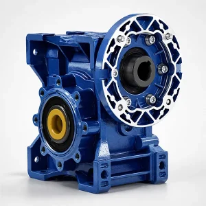
WPWDKS vs NMRV Aluminium — A Practical Comparison
Korean OEM designers regularly ask which worm gear reducer family — WP cast-iron or NMRV aluminium — is "better". The honest engineer's answer is that they are designed for different duty profiles. The table below frames the trade-offs head-to-head at an equivalent torque output of about 200 Nm.
| Criterion | WPWDKS (Cast Iron) | NMRV (Aluminium) |
|---|---|---|
| Housing weight (≈200 Nm class) | 12–14 kg | 5–6 kg |
| Recommended duty | 16–24 h/day continuous | 8 h/day single-shift |
| Oil-bath thermal limit | 95 °C sustained | 80 °C sustained |
| Resistance to particulate ingress | Excellent — hard surface | Moderate — softer aluminium |
| Wash-down compatibility | Painted only — corrosion risk | Anodised aluminium IP67 |
| Vibration damping | High — graphite microstructure | Moderate |
| Relative price | 1.5–1.8× | 1.0× (baseline) |
| Best-fit applications | Heavy industry, hot ambient | Packaging, doors, light conveyors |
If the application calls for daily wash-down or strict weight constraints, choose NMRV aluminium. If duty cycle exceeds 12 hours per day, ambient temperature exceeds 35 °C, or particulate contamination is a concern, the WPWDKS worm gear reducer is the right specification. Mixed-duty installations sometimes pair both worm gear reducer types: WPWDKS on the main process drives, NMRV on auxiliary doors and indexing tables.
Lubrication, Service Intervals & Run-In Procedure
A fresh WPWDKS worm gear reducer ships with a mineral CLP 220 factory fill suitable for ambient operation up to 40 °C. The first oil change matters more on cast-iron WP-series worm gear reducer units than on aluminium NMRV units because the larger oil bath traps more bronze run-in particulate during the first 100–500 hours of operation. Drain the factory fill at 500 operating hours, flush the cavity with 50% of the refill volume, drain again, and refill to the sight-glass mark.
After the run-in change, follow a 4,000-hour or 12-month service interval (whichever is shorter) for mineral oil; 8,000-hour or 24-month for synthetic PAG. Sustained operation above 80 °C oil temperature should trigger a switch to PAG regardless of installation age. The WPWDKS housing carries a clearly visible sight glass on the side wall and a magnetic drain plug on the bottom — the magnetic plug catches steel debris from any worm shaft wear and is the most useful single source of condition-monitoring data the operator has.
For installations subject to extended idle periods (more than 30 days without rotation), the worm gear reducer's bronze wheel can develop dry-spot corrosion at the load contact zone if the lubricant film breaks down. We recommend a 30-second rotation every 14 days during idle to redistribute the oil film — a small ritual that adds years to wheel life.
Customisation Options for OEM Specifications
Catalogue WPWDKS worm gear reducer variants cover roughly 80% of orders. The remaining 20% require one or more customisations from the list below — none of which carry tooling fees on production orders of 30 units or more, and most of which we accommodate on small-quantity samples too.
Output shaft modifications. Standard worm gear reducer solid shaft length is 80 mm; we routinely build extensions to 120 mm. Splined outputs (DIN 5480 series), imperial keyways and double-extended outputs (both ends machined) are supported on all frame sizes from WPWDKS70 upwards.
Non-standard ratios. The catalogue stops at i=60 because beyond that single-stage worm gear reducer efficiency drops below 50% and a two-stage helical-worm hybrid becomes more practical. For specialty applications, we will quote i=70, i=80 or i=100 single-stage at a small custom-tooling charge.
Special paints & coatings. RAL 5015 sky blue or RAL 7001 silver grey are catalogue stock. Custom RAL colours require a minimum of 5 units; epoxy or polyurethane two-pack coatings for offshore and saline environments are quoted per project.
Backstop / anti-reversing devices. A roller-clutch backstop on the worm shaft input prevents reverse rotation under shock load. This is specified on inclined conveyor drives, hoists and certain stretcher-roller configurations where self-locking via the worm geometry alone is insufficient for safety classification.
Related & Complementary Products in Our Range
Industrial drive trains seldom consist of a worm gear reducer alone. Below are four product ranges that pair logically with the WPWDKS worm gear reducer — distinguishing carefully between actual drive-train companions, internal spare parts, and parallel reducer families from our Korean worm gear reducer manufacturer catalogue.
Drive shafts (transmission companion). A drive shaft sits in the drive train between the prime mover and the gearbox input, or between the gearbox output and the driven machine. On a long dyeing range or a multi-roller kiln drive, the WPWDKS often connects to its load through a CV-jointed drive shaft with a slip section to absorb thermal expansion. See PTO & CV joint drive shafts for matched assemblies.
Worm and worm wheel pairs (internal spare parts). The bronze wheel and steel worm shaft inside the WPWDKS are the principal wear components. After 25,000–35,000 hours of duty, the wheel typically reaches its wear limit while the housing and bearings are still serviceable. A worm-and-wheel re-tooth kit lets a maintenance team rebuild the gearbox in place at roughly one-third the cost of a complete unit replacement. Sized for every WPWDKS frame at worm and worm wheel pairs.
Planetary gear reducers (sister product line). When the application calls for high efficiency (≥ 95%) and accurate positioning rather than self-locking holding torque — for example servo-driven indexing tables or precision rotary axes — a planetary gearbox is the appropriate alternative reducer family. Same supplier, different drive principle. See planetary gear reducers for the in-line and right-angle ranges.
Agricultural gearboxes (industry-specific sister line). For tractor PTO drives, rotary tiller heads, irrigation pivot reducers and feed-line conveyors, our agricultural gearbox catalogue applies similar bronze-wheel-and-steel-worm technology in field-rated housings with reinforced sealing for outdoor exposure. Browse the range at agricultural gearbox replacements.

Drive Shafts (transmission companion)

Worm Gear Pairs (internal spare parts)

Planetary Gearboxes (sister product line)

Agricultural Gearboxes (sister product line)
WPWDKS Application Engineering FAQ
Below are the questions our applications engineers field most frequently from Korean and Japanese customers specifying the WPWDKS worm gear reducer. Each answer reflects field experience and verified bench-test data rather than catalogue marketing copy.
Q: How is the WPWDKS configuration different from WPWDA or WPWDV?
A: The last letter of the WP code denotes input/output orientation. WPWDKS has vertical motor input shaft and horizontal output. WPWDA has horizontal input via flange. WPWDV has vertical output and horizontal input. WPWDX has double-extended output (both ends machined). All four worm gear reducer variants share the same internal worm-and-wheel geometry — the housing castings differ to support the chosen orientation.
Q: How do I read the centre distance and pick the right WPWDKS frame?
A: Centre distance "a" is the perpendicular distance between the worm shaft axis and the wheel axis, measured in millimetres. It is the primary capacity indicator on every WP-style worm gear reducer. For the WPWDKS worm gear reducer match the input power band first, then verify the catalogue ratio gives you the output rpm you need within the n₂ table. Output torque scales roughly with the square of centre distance.
Q: Can the WPWDKS run on mineral oil or do I need synthetic from day one?
A: Mineral CLP 220 is the factory fill and is sufficient for ambient operation up to 40 °C with 8–12 h/day duty. Above 40 °C ambient or 16+ h/day continuous duty, switch to synthetic PAG ISO VG 220 — it doubles oil-change interval and runs measurably cooler. Synthetic is non-negotiable above 80 °C oil-bath temperature.
Q: Is the bronze wheel really ZQSn10-3 or a cheaper substitute?
A: Yes — full ZQSn10-3 (10% Sn, 3% Zn, balance Cu) per Chinese standard GB/T 1176, which corresponds to CuSn10Zn2 in EN 1982. Material certificates are issued from each casting heat. Cheaper bronze grades in worm gear reducer wheels like ZQSn6-6-3 exist but show roughly 40% shorter wheel life under continuous duty — we do not substitute without explicit customer approval and a corresponding price reduction.
Q: What is the typical service life on a 16-hour textile dyeing duty?
A: On a properly sized WPWDKS80 i=30 with synthetic PAG and 4,000-hour oil intervals, expect 30,000–40,000 operating hours before the bronze wheel reaches its wear limit. That is roughly 7–10 years of 16-h/day duty. Worm shaft and tapered roller bearings typically last twice that. Housing service life on cast iron is effectively the life of the plant.
Q: Does the WPWDKS have a built-in backstop?
A: Not as standard. The bronze-on-steel worm gear reducer geometry is self-locking at i ≥ 30 under static load, but self-locking is a friction phenomenon and should not be relied on for safety-classified hoist or inclined-conveyor duty. We offer an optional roller-clutch backstop on the worm shaft input for an additional charge — this is the correct specification when a positive anti-reverse function is required.
Q: Can the WPWDKS be mounted with the input shaft pointing downwards?
A: Yes — the worm gear reducer can be inverted with a relocated breather plug and a properly specified shaft seal. This is sometimes done on overhead worm gear reducer installations where the motor sits below the gearbox in a service ceiling. Specify the inverted orientation at the order stage so the housing ships pre-configured — flipping the breather and seal in the field is doable but doubles installation time.
Q: What lead time should I plan for a WPWDKS80 order to Korea?
A: Catalogue WPWDKS worm gear reducer frames 50 through 100 are typically ex-stock at our Korean warehouse with 2–5 working day delivery to most industrial cities. Frames 120 and above ship on a 3–4 week lead time from the Hangzhou factory. Custom outputs, paints or backstops add 2 weeks to either case.
Field Reports from Asian Industrial Plants
The feedback below is gathered from process engineers, plant maintenance leads and OEM designers who have specified or serviced WPWDKS units over the past 12 to 18 months across Korea, Japan, Vietnam and Thailand. Where customers have given permission, technical detail and frame size are preserved verbatim alongside the worm gear reducer frame size.
Kim Seo-yun, Process Engineer, Daegu textile cluster (Q1 2026)
"Replaced 18 worn cast-iron worm units on a 1.8 m continuous dyeing range with WPWDKS80 i=30. Six months of 22 h/day duty later, oil temperature is averaging 68 °C — the previous units sat at 82 °C and we changed oil every 1,800 hours. Now we are projecting a 4,000-hour interval with PAG. Maintenance budget impact is real."
Tanaka Hiroshi, Plastic Processing Manager, Osaka (Q4 2025)
"Six WPWDKS50 i=20 units on extruder feed augers, 0.55 kW motors, three-shift duty for ten months. Zero unplanned stops. The vertical input let us mount the motors above the auger drives — saved about 600 mm of floor space per extruder, which mattered on our line layout."
Choi Hyun-woo, Plant Maintenance Lead, Icheon ceramic factory (Q2 2025)
"Twelve WPWDKS100 units installed on a 50 m roller-hearth tile kiln. Self-locking holds rollers stationary during power dips — that is the feature that sold us. Eight months later, we have not lost a single load of tiles to drift. Service Korea office answered our two warranty questions inside a working day."
Nguyen Van Hai, Procurement Lead, Ho Chi Minh City furniture plant (Q3 2025)
"Eight WPWDKS80 i=40 on wide-belt sander feed rollers, 1.5 kW motors. Sawdust is constant in our shop and the cast-iron housings have shrugged it off where the previous aluminium units developed scoring on the output bore inside a year. Twelve months in, no complaints."
Jung Hae-rin, OEM Designer, Incheon (Q4 2025)
"Specified WPWDKS135 with backstop on a 12 m inclined chip conveyor for a stamping plant. The backstop is the critical safety feature here — power loss during heavy load would otherwise let the chip column reverse-drive the gearbox. Documentation pack arrived complete with the backstop datasheet on day one."
Somchai Phongsri, Glass Plant Engineer, Rayong (Q3 2025)
"Six WPWDKS135 i=50 on the float-line annealing lehr roller drives. Speed stability is what matters here and the worm damping helps the closed-loop servo control hold ±0.3% accuracy. Quieter than the German brand we replaced, and at about 65% of the price."
Park Min-jun, Maintenance Engineer, Ulsan industrial machinery (Q1 2026)
"Standardised on WPWDKS frames across two new heavy-machinery projects. The frame-size matrix and the ratio table mean I can size 90% of orders without escalating to the supplier — that saves a quotation cycle. ZQSn10-3 wheel material certificate arrives with every shipment."
Additional information
| Editor | Cxm |
|---|
Related products
-
EP-NMRV Aluminum Worm Gearbox with Output Flange | RV-Series Worm Gear Reducer
-
FU1000 Worm Gearbox Replacement | Fenner FU-Type Horizontal Foot-Mount Equivalent
-
WPWA Worm Gearbox | Horizontal Flange-Input WP Series Worm Reducer
-
WPWO Worm Gearbox | Output-Flange WP Series Worm Reducer
-
MRV050 Worm Gear Reducer | Worm Gearbox


